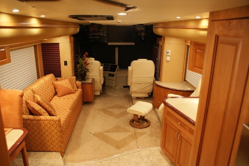
The Slide-out Control System is setup for three slide-out rooms: two living room - left & right, each with two electric motor actuators; one bedroom - left, with one electric motor actuator. Each slide-out room has two air cylinder locks which are sequenced by the Slide-out Control System. The airlocks are only extended when the slide-out rooms are fully extended or fully retracted.

The slide process……
The Slide-out Control System applies power to the electric motor actuator(s) to move the slide-out room In or Out when the respective Room Motion switch is pressed. The Slide-out PLC (programmable logic controller) examines the state of five parameters:
- Ignition switch in the Accessory position,
- Parking brake,
- System air pressure,
- Lock state,
- IN/OUT limit switches
before processing the IN/OUT command from the respective Room Motion switches. When all parameters are in the correct states, the Slideout PLC Controller sequences the air locks and executes a IN/OUT command. The power comes from from panel #2, circuit breaker in the Bedroom 120VAC load center to a Black box 120vac to 27vdc converter. Find this converter plugged into a dedicated outlet in the bay behind the slide lock valves and controller. The converter provides power to the 1) Slide-out PLC Controller, 2) the Dual Motor Synchronizer, and 3) the slide-out room motor actuators.
NOTE: Circuit Breaker 4B in the Bedroom must be ON to operate slide-out room. If the locks are manually extended with the slide-out room in an intermediate position, the locks will cause severe damage to the slide-out room sides.
4-7.2.1 Room Motion Switch Assembly
The Room Motion Switch Assembly provides the slide-out room IN & OUT control switches along with eight status LED indicators. The IN switch moves the room inward as long as the switch is depressed. The IN switch should remain pressed until the LOCKED LED lights indicating that the Room In sequence has completed. The Room In motion can be stopped at an intermediate state by releasing the IN switch. The room in motion can resume by pressing & holding the IN switch or the Room Out motion can proceed by pressing the OUT switch. The OUT switch moves the room outward as long as the switch is depressed. The OUT switch should remain pressed until LOCKED LED lights indicating the Room Out sequence has completed.
The Operator Control panel will light up when there is 27volts found at the PLC controller.
Associated Attachments .........
450Lxi Owners Manual Slide Room section 4.7
Slide Room Wire Diagram schematic
Owner Awareness ..................
Slide Room locks are powered by air pressure. The three Norgen electric over pneumatic valves, located in the driver side bay between the generator and the slide controller, have proven to be sensitive to moisture that may have entered the air tank from a faulty air dryer on the 120v compressor located in the bay under the driver.
The programmable logic controller PLC board and slide engineering was subcontracted to an outside company and not a BlueBird component or a typical RV slide engineering supplier. The builder of the slide out controller for the M450 is: Hamilton ITS Inc. located at 1416 Harris Industrial Blvd, Vidalia, GA 30474. Contact Mr. Ray Hamilton phone 877-206-5164, web site http://www.hamiltonits.com These rooms are robust and employ a simple process to open but utilize a complex adaptive industrial control system. The computers that operate the system are built to industrial standards and made to adapt to factory changes in product runs. It's quite overbuilt and is very robust and has easily manageable programming logic now that owners have the process explained here.
